2016年11月20日日曜日

ラジオ・キット KM-88 不具合原因解析と対策(改良設計) 暫定版

KM-88 スーパーヘテロダインラジオの動作方式

概要 KM-88は、RF MixerをTR1, 局部発振器をTR2でそれらの回路を独立に分離しているのを特徴とするスーパーヘテロダイン式ラジオである。

(一般家庭用、趣味のキット用として、安価な従来式スーパーヘテロダインラジオは、次の2タイプがある。

A. 一石のトランジスタでミキサーと局部発振器を同時動作させるタイプ
B. 二石のトランジスタで、ミキサー回路と、局部発振器を分離したタイプ

KM-88は後者Bのタイプで、ミキサー回路と、局部発振器回路が独立しているので、それぞれの回路のトランジスタに独立したバイアス電圧を与えることができ、それぞれの回路動作条件を若干だけ設計しやすく、動作も安定する設計意図による構成になっている。)


図1. KM-88 オリジナル回路と改良設計の概略


2. 回路構成と動作方式

(1) TR1は、ベース端子から L+VC1 同調回路で選択した放送局高周波AM電波を入力、局部発振器(TR2によるOSC)のサイン波電圧をエミッタ端子からC2経由で入力、両者のRF信号をアナログ乗算して周波数変換動作させ、455KHz帯の中間周波数帯を、IFT-1に出力する。

(2) TR2は、局部発振器(OSC)を構成。発振周波数はOSCコイルとVC2の同調回路より定まる。

(3) TR3,TR4は、IFT 455KHz帯の中間周波増幅帯高周波アンプを構成し、ここで高い受信感度利得を得る。 TR3のベースにはC11、R8で時定数の定まるAGC電圧がかかるAGC(自動利得制御)がかかる。TR4のベースは固定バイアス電圧により固定利得で動作する。

(4) D1のダイオード、R10,VR,C8,C9は、AM変調波を検波するダイオード検波回路を構成する。また、ダイオードから出力されるマイナスDC電圧をAGC電圧としてIF初段のTR3にフィードバックする。

(5) TR5,TR6はトランジスタ2段の小信号低周波増幅アンプを構成する。

(6) TR7、TR8は、プッシュプルによる電力増幅アンンプでスピーカSPを鳴らす。

3. 課題

(1)TR1がミキサー回路として周波数変換動作を行うためには、アナログ乗算器としてバイアス動作点を設定する必要がある。しかし、この一石アナログ乗算回路は、ギルバートセル型アナログ乗算のような優れたアナログ乗算特性が出せない電気的特性上の課題をかかえたまま、現在でも課題が解決されていない。

TR1の負荷が、iFT同調回路で、インピーダンスを下げてコレクタに接続されてはいるが、負荷インビーダンスが虚数成分(リアクタンス成分)を持つために、良好なアナログ乗算器特性を出せない原因になっている
TR1の負荷インピーダンスは、理想的には純抵抗成分であるのがアナログ乗算動作に必要な基本条件と考えられる。

(2)TR1のOSCとの結合抵抗C2 = 0.005uFが大きすぎる。このため、OSCの発振が不安定または停止し、ラジオが全く聞こえない現象を起こす原因になっている。

(3)OSC回路のC3は不要。

(4)回路構成上、TR1のミキサー回路と、OSC TR2の電気的結合が強すぎる。このため、両者の回路をそれぞれどちらも安定動作させる条件の同時成立が難しくなっている。
(どちらかの回路動作に不安定動作が現れると、他方に悪影響が及ぶ。)

(5)OSCが安定に発振するためには、TR2のバイアス電圧ポイント設定が適切である必要がある。しかし、このバイアス電圧ポイント設定が適正でないと、全く発振しないか、異常発振の原因になっている。

(6)OSC TR2コレクタ側に接続されるOSCトランスの2次側コイルから、Vccパタンを経由して、強い発振波RF電圧が漏れる。このため、これをバイパスする高周波特性の良いパスコンが必要だが、回路上に明確にはない。
(C12は電解コンデンサ(アルミ電界コン)なので良好な高周波バイパス特性が期待できない。)

このため、Vccと交流的にショート状態にあるGNDラインー>C1ー>TR1ベースへOSC発振電圧が流れ込みやすく、TR1が異常発振する原因になっている。

(7) iFT1, iFT2, iFT3はそれらは、一次側、ニ次側が密結合になっているので、iF増幅回路の総合利得が高いため、自己発振しやすい構造になっている。

(8) iFT1, iFT2, iFT3はそれらは一次側の中間タップから電源電圧をとっているが、このコイル構造は、LC同調回路の同調周波数が大きくずれやすい特性があるため、iFTのそれぞれが455KHzから同調周波数が大きく離れて同調しやすくなっている。
為に、iF増幅回路の利得がほとんどなく無くなり、ラジオ放送が何も聞こえない現象を起こす原因になりやすい。

(9) (8)とは逆に、TR1, TR2 のIF増幅器は、iFTが同調すると利得が高くなるので、構造的に自己発振が起こりやすいリスクも同時に持っている。

(10) TR4のバイアス抵抗は、TR4の利得に大きく影響する。このバイアス電圧が適切でないと、十分な感度・利得が得られないか、逆に利得過剰で、異常発振を起こしやすい特性がある。

(11)ダイオードは、ゲルマニウム・ダイオードが好んで使用されるが、ダイオード検波回路の動作について従来検波理論に誤りがある。この検波回路動作は、高周波特性モデルで計算解析されるべきであるが、これが必ずしも良く知られておらず、微小電圧でのDC特性と、低い周波数での整流とピークホールドという誤った包絡線検波理論で説明されていることが多い。

ダイオードはAM検波を実際に実用的に検波動作をしてはいるが、それは被変調波成分LSB,USB信号と、キャリア周波数の差分の低周波信号の周波数変換動作によるものである。

この検波特性は、ダイオー電流の指数関数特性に由来するので、3次、4次以上の高調波歪みが発生するのを避けられない課題がある。
(ピークを補完するダイアゴナル歪みが発生するという従来理論は誤りと考えられる。)

(12)ダイオードの出力には、高い信号レベルの455KHz帯域周波数が出力され、これをC8でグランドに落とし、R10+C9によるLPFで減衰させている。しかし、その減衰量が不十分で、小信号AFアンプに漏れ出し、増幅されてしまう結果を招く。

TR5は、このIF信号を増幅から防ぐ手段が回路上にない。
T1一次側コイル+C10のLC共振回路により、この検波回路出力から漏れたIF信号増幅を抑える回路が見られるが、TR5,TR6によるIF信号増幅動作を抑えることが十分にできていない。

(13) R17は、動的に変化している電流に比例して電圧降下が起こるので、TR1,2,3,4,5,6にその変動したDC電圧が加わる課題がある。

(14) TR5以降のトランスを用いたAFアンプは周波数特性が悪いので、良好な音質を得られない。

(15) 6V電池の利用が想定されているが、現在のポータブルラジオは3V動作が主流であるが、全体の回路構成が3V等の低電圧電源動作に向いていない設計になっている。

3. 対策(改良設計)


3.1 局部発振器の安定化対策

局部発振器を単独で発振安定に改良設計する。

図3.1 局部発振器の安定化対策の過渡解析結果


3.2 ラジオ受信部の改良設計


AF増幅部を除くラジオ受信部の改良設計を行う。


3.2 AF増幅部を除くラジオ受信部の過渡解析結果


参考資料:

後述とする。

Revision: 初版 2016/11/20

ブログ記事目次へ戻る


2016年11月11日金曜日

3V動作 トランスレス型 3 BJT トランジスタ 低周波パワー・アンプの設計


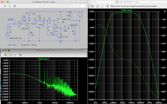
乾電池3Vで動作できるポータブルラジオ用にスピーカを鳴らせる3石トランジスタ使用低周波ミニ・パワーアンプを設計した。

1. 前段LPF無しの増幅動作


図1 過渡解析結果


図2 AC解析結果


過渡解析結果からは、高調波歪みは多少あるが、実用範囲にあると思われる。
約20dBもの電圧利得が得られた。

しかしトランジスタの高周波特性が良すぎるため、中間周波数455KHzでも相当の利得がでてしまう。


2. 高周波ゲインを下げる改良

上記1.の周波数特性を、高周波領域で十分下がるように初段に 10KΩと0.01uFによるLPFをつけた。

その結果、総合利得はぼぼ同一で、中間周波数455KHz以上で十分に利得が下がる効果が得られた。


図3 過渡解析結果


図4 AC解析結果


ブログ記事目次へ戻る


2016年11月5日土曜日

Synchronized AM demodulator by using “IQ demodulator” and calculations of square-multiplying and square root 

Synchronized AM demodulator by using “IQ demodulator” and calculations of square-multiplying and square root (Preliminary)
IQ(直交)復調器と、自乗、加算、平方根計算を使った数値演算式AM同期検波方式理論
(C) Noboru, Ji1NZL, Nov. 2, 2016


[Abstract] 
AM receivers can cancel the change of the phase on the received signal by using an IQ demodulator and the math operation Vout = √(I(t)^2+q(t)^2). 
The IQ demodulator here may configured by analog circuit and that the math operation Vout = √(I(t)^2+q(t)^2) can be calculated by some MPU or DSP. This AM detector can get good quality of sound with very low distortion.

 Fig.1 An architecture of AM synchronized detector

1. How the AM synchronized demodulator works

AM RF signal received on the radio expressed as the equation (1). 
Here, I assume that Vam changes the phase θ(t)[rad] on the propagation path of the AM RF/ ( E/M ) wave. 

Vam= ( Vdc+x(t) )*Vc*sin(ωc*t+θ(t)) …(1)  

Vdc : DC voltage at AM modulator. Unit is [V].
x(t) : Baseband signal function for AM modulator. Unit is [V].
Vc  : Carrier peak voltage that AM receiver receives. Unit is [V].
ωc : Angular frequency of the AM modulator. Unit is [rad・Hz].
fc  : Frequency of the carrier ωc. Unit is [Hz].

There is a problem that the signal strength of decoded tone changed by this phase change. For example, when the receiver used the oscillator frequency = π/2 [rad] shifted for the equation (1), the decoded signal becomes 0. It means there is no tone. Or we feel it as “fading” phenomenon as time goes on.

The AM decoder here synchronized with the phase of the carrier, fix this problem.
Assume the baseband signal is a sine wave voltage of single audio frequency defined as (2) here.

x(t)=Vs*sin(ωs*t) …(2)  

Vs  :  Peak voltage of (2). Unit is [V].
ωs : Angular frequency of a sine baseband signal. Unit is [rad・Hz].
ωs = 2πfs …(3)
fs : Frequency of baseband sine wave. Unit is [Hz].

The voltage of the oscillator Vosc is expressed as

Vosc = Vo*sin(ωc*t) …(4)

Vo : Peak voltage of (4). Unit is [V].

At the equation (1), 

sin(ωc*t+θ(t)) = sin(ωc*t)*cos(θ(t))+cos(ωc*t)*sin(θ(t))  … (5)

Then (1) becomes


Vam= Vc*{Vdc+ Vs*sin(ωs*t)}* { sin(ωc*t)*cos(θ(t))+cos(ωc*t)*sin(θ(t)) } …(6)
      = Vc{ Vdc*sin(ωc*t)*cos(θ(t))+Vdc*(cos(ωc*t)*sin(θ(t))) )
              +Vs*sin(ωs*t)*sin(ωc*t)*cos(θ(t))+Vs*sin(ωs*t)*cos(ωc*t)*sin(θ(t)) } …(7)

Since V3 = Vam*Vosc , then (7)x(4) becomes V3,

V3 = Vc{ Vdc*sin(ωc*t)*cos(θ(t))+Vdc*(cos(ωc*t)*sin(θ(t))) )
              +Vs*sin(ωs*t)*sin(ωc*t)*cos(θ(t))+Vs*sin(ωs*t)*cos(ωc*t)*sin(θ(t)) } * Vo*sin(ωc*t)

=Vc*Vo{ Vdc*(sin(ωc*t))^2*cos(θ(t))+Vdc*(sin(ωc*t)*cos(ωc*t)*sin(θ(t))) )
            +Vs*(sin(ωs*t)*sin(ωc*t))^2*cos(θ(t))+Vs*sin(ωs*t)*sin(ωc*t)*cos(ωc*t)*sin(θ(t)) }

=Vc*Vo{ (sin(ωc*t))^2* {Vdc*cos(θ(t)) + Vs*sin(ωs*t)*cos(θ(t))}
            + (sin(ωc*t)*cos(ωc*t)*{ Vdc*sin(θ(t)) + Vs*sin(ωs*t)*sin(θ(t)) } }

=Vc*Vo{ (sin(ωc*t))^2* (Vdc + Vs*sin(ωs*t))*cos(θ(t))
          + (sin(ωc*t)*cos(ωc*t)) *(Vdc + Vs*sin(ωs*t))*sin(θ(t)) }  …(8)


Here,
(sin(ωc*t))^2 = (1/2)*(cos(2*ωc*t)-cos(ωc-ωc)) = (1/2)*{cos(2*ωc*t)-1}  …(9) 
sin(ωc*t)*cos(ωc*t) =(1/2)*sin(2*ωc*t) …(10)

Replace (sin(ωc*t))^2 and sin(ωc*t)*cos(ωc*t) in (8) by (9) and (10)
Then

V3 = Vc*Vo{  (1/2)*{cos(2*ωc*t)-1} * (Vdc+Vs*sin(ωs*t))*cos(θ(t)) + (1/2)*sin(2*ωc*t) *(Vdc+Vs)*sin(θ(t)) } 
    = Vc*Vo{ (1/2)*cos(2*ωc*t)*(Vdc+Vs)*cos(θ(t)) -(1/2)* (Vdc+Vs)*cos(θ(t)) + (1/2)*sin(2*ωc*t) *(Vdc+Vs*sin(ωs*t))*sin(θ(t)) }  …(10)

Very high RF frequency voltage cos(2*ωc*t) and cos(2*ωc*t) can be remove from (10) by LPF,

Then
V-i = Vc*Vo{ -(1/2)* (Vdc+Vs*sin(ωs*t))*cos(θ(t)) }  
    = -(1/2)*Vc*Vo{ (Vdc+Vs*sin(ωs*t)) *cos(θ(t)) } …(11)

V2 is -π/2[rad] shifted signal of the oscillator (4),

V2= Vo*sin(ωc*t-π/2) = -Vo*cos(ωc*t) …(12)

Here the equations (4) and (12) configures as so-called an “orthogonal oscillator”. 
They may generate orthogonal sine waves or square (pulse) waves that they are shifted -π/2 [rad] each other.

When the orthogonal oscillator generates sine waves, the mixer devices must be used as analog multipliers.

When the orthogonal oscillator generates square (pulse) waves, analog switches can be used as the mixer devices. 

Get V4 = Vam * V2, 
V4 = Vc{ Vdc*sin(ωc*t)*cos(θ(t))+Vdc*(cos(ωc*t)*sin(θ(t))) )
            +Vs*sin(ωs*t)*sin(ωc*t)*cos(θ(t))+Vs*sin(ωs*t)*cos(ωc*t)*sin(θ(t)) } * (-Vo*cos(ωc*t)) }
    = -Vc*Vo{ Vdc*sin(ωc*t)*cos(ωc*t)*cos(θ(t))+Vdc*((cos(ωc*t)^2)*sin(θ(t))) )
                    +Vs*sin(ωs*t)*sin(ωc*t)*cos(ωc*t)*cos(θ(t))+Vs*sin(ωs*t)*(cos(ωc*t))^2*sin(θ(t)) }
    =  -Vc*Vo{ sin(ωc*t)*cos(ωc*t){Vdc*cos(θ(t)) +Vs*sin(ωs*t)*cos(θ(t))}
                    +((cos(ωc*t)^2) {Vdc*sin(θ(t))+ Vs*sin(ωs*t)*sin(θ(t))}  }
  =  -Vc*Vo{ sin(ωc*t)*cos(ωc*t){Vdc +Vs*sin(ωs*t)}*cos(θ(t))
                  +((cos(ωc*t)^2) {Vdc+ Vs*sin(ωs*t)}*sin(θ(t))) } …(13)

Here,
(cos(ωc*t))^2 = (1/2)*(cos(2*ωc*t)+cos(ωc-ωc)) = (1/2)*{cos(2*ωc*t)+1}  …(14) 

sin(ωc*t)*cos(ωc*t) =(1/2)*sin(2*ωc*t) …(10)

V4 = -Vc*Vo{  (1/2)*sin(2*ωc*t) *{Vdc +Vs*sin(ωs*t)}*cos(θ(t))
                  +((1/2)*{cos(2*ωc*t)+1}) {Vdc+ Vs*sin(ωs*t)}*sin(θ(t))) }
    = -Vc*Vo{  (1/2)*sin(2*ωc*t) *{Vdc +Vs*sin(ωs*t)}*cos(θ(t))
                  +((1/2*Vdc)*{cos(2*ωc*t)) + (1/2){Vdc + Vs*sin(ωs*t)}*sin(θ(t))} ) } …(15)

Very high RF frequency voltage sin(2*ωc*t) and cos(2*ωc*t) can be remove from (15) by LPF,

Then
V-q= -Vc*Vo{ (1/2){Vdc + Vs*sin(ωs*t)}*sin(θ(t))} ) } 
= -(1/2)*Vc*Vo*{Vdc + Vs*sin(ωs*t)} *sin(θ(t)) } …(16)

Here, define K(t) is as
K(t) ≡ -(1/2)*Vc*Vo*{Vdc + Vs*sin(ωs*t)} …(17)

Then (16) can be written as
V-q = K(t)*sin(θ(t)) …(18)

and (11) can be written as
V-i = K(t)*cos(θ(t))  …(19)

By using (18) and (19),

V-i^2 + v-q^2 = {K(t)*cos(θ(t)) }^2 + {K(t)*sin(θ(t))}^2
                    = K(t)^2*{cos(θ(t))}^2 + K(t)^2*{sin(θ(t))}^2 
                    = K(t)^2*{ {cos(θ(t))}^2 + {sin(θ(t))}^2 }  … (∵ {cos(θ(t))}^2 + {sin(θ(t))}^2 =1 )
                    = K(t)^2

∴ √(V-i^2 + v-q^2) = K(t)
                            = -(1/2)*Vc*Vo*{Vdc + Vs*sin(ωs*t)} …(20)

The equation (20) is the same as AM decoded voltage Vout on the Fig.1.
∴ Vout = -(1/2)*Vc*Vo*{Vdc + Vs*sin(ωs*t)} 
            = -(1/2)*Vc*Vo*Vdc  - (1/2)*Vc*Vo*Vs*sin(ωs*t) …(21) 

The equation (21) does not have the variable θ(t) in these parameters.
And Vo and Vdc are constant value. 
The DC voltage -(1/2)*Vc*Vo*Vdc [V] can be removed by some condenser such as 1uF.
Vc (signal strength) can change according to the time goes. 
However it can be nearly constant by using AGC (Automatic Gain Control) in the receiver.

This means output signal voltage Vout is extracted the baseband signal Vs*sin(ωs*t) as the output “Vout” from Vam, 
it is independent of change value of the phase θ(t),
and the AM Synchronized reception is possible by using the architecture of Fig.1.

I draw the Fig.1 by referencing the schematic[1] and changed the delay function to configure an orthogonal OSC(oscillator). that generates a 1MHz sine or square (pulse) wave and a π/2 [rad] shifted one.

If voltages V-i and V-q are sampled by A/D convertors, MPU or DSP can calculate Vout by the equation (21). 


Fig.2 is an example of simulation result of the transient analysis by LTspice iV developed by (C) Linear Technology inc. 
The quality of the detector is pretty better than the traditional diode detector.


Fig.2 Simulation result of the transient analysis by LTspice iV 

 
                        Fig.3  An example of actual work of demodulation by "IQ demodulator" 


      Fig.4  An example of assembling of "IQ memodulator" RF front end PB

2. Subjects

(1) Frequency stability of the orthogonal oscillator and error of demodulated tone

    The orthogonal signal oscillator have to have good frequency stability such as a few Herz.
    But old type of PLL that sets the frequency such as 100Hz every steps is used, 100Hz low beat can occur.
    Frequency error for the orthogonal oscillator can affect the tone difference. Especially, when listening music or songs. 
    It seems that human’s ears are very sensitive for 8Hz frequency drift.
    Accuracy and stability of frequency for the orthogonal oscillator is very important.  
    Latest DDS can satisfy this accuracy.

(2) Sampling noise of ADC (AD converter)
    The sampling noise of ADC (AD convertor) may affect the RF input of the receiver. It must be minimized.

(3) Switching noise of Analog switches
    When analog switches are used as the orthogonal mixer, they generates some noise. However, it can removed by LPF.
    In the actual experiments, they are practical enough.

(4) Wide dynamic range of AM demodulator
    The traditional diode AM detector so called “Peak detector” or “Envelope detector” generates harmonics tone such as 2KHz, 3KHz, …. if the baseband frequency is 1KHz used. This is derived from the electric characteristics of exponential function on the diodes current.  { The current on diode is expressed as  “ i = Is*(exp(K*v)-1) “. }
This demodulator can have much wider dynamic range for the baseband signal swings then the diode detector. 
Because the demodulator by analog multipliers or analog switch can have wide dynamic range without tone distortion such as the traditional diode detector.

(5) Programmable LPF/BPF
The LPF/BPF at I/Q output sides can be defined by the software on the DSP or MPU. Eg. FIR filter, IIR filter.
These LPF/BPF also can be configured by the analog circuit such as CR filter, LC filter, or other filter used with OP amps.  

References:
[1] The schematics of “AM synchronous detector” by the author Mr. “Kaikyou no Kaze” / “The wind from the sea” 
(Copyright of the schematics is reserved and is respected as nice knowledge of the author.)

Return to INDEX

2016年11月3日木曜日

コイルを使わないGIC同調回路とそれを使ったダイオード検波AMラジオ

コイルを使わないGIC同調回路とそれを使ったダイオード検波AMラジオを構成してみました。
目標は、IC(集積回路)にコイルを使わずに同調回路やマッチング・フィルタを組み込むことを視野に入れています。


図1 GIC同調回路を使ったダイオード検波AMラジオの過渡解析結果


図2 GIC同調回路を使った同調回路の周波数・位相特性解析結果
(長波〜中波〜短波)


図3 従来式 LC同調回路を使った同調回路の周波数・位相特性解析結果
(長波〜中波〜短波)


参考資料:
[1]アナログ回路 培風館 "オペアンプによるGIC回路"
(内容が古いので現代に適応する改訂が望まれます。)


ブログ記事目次へ戻る